1. What is structural instability?
2. What are the main types of instability phenomena in structures?
Structural instability can be classified into two main types: global and local instability. Global instability refers to the overall deformation or failure of the entire structure, while local instability occurs only in specific parts of the structure but can still affect the entire structure.
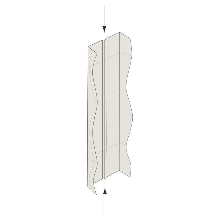
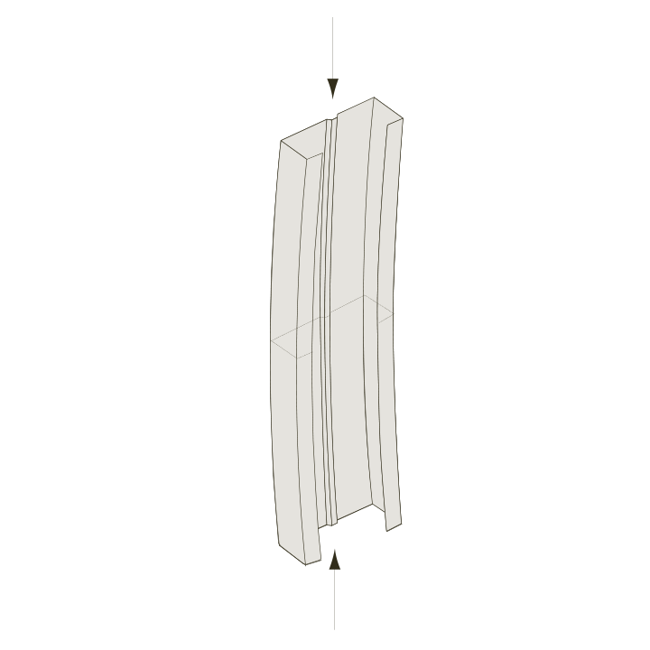
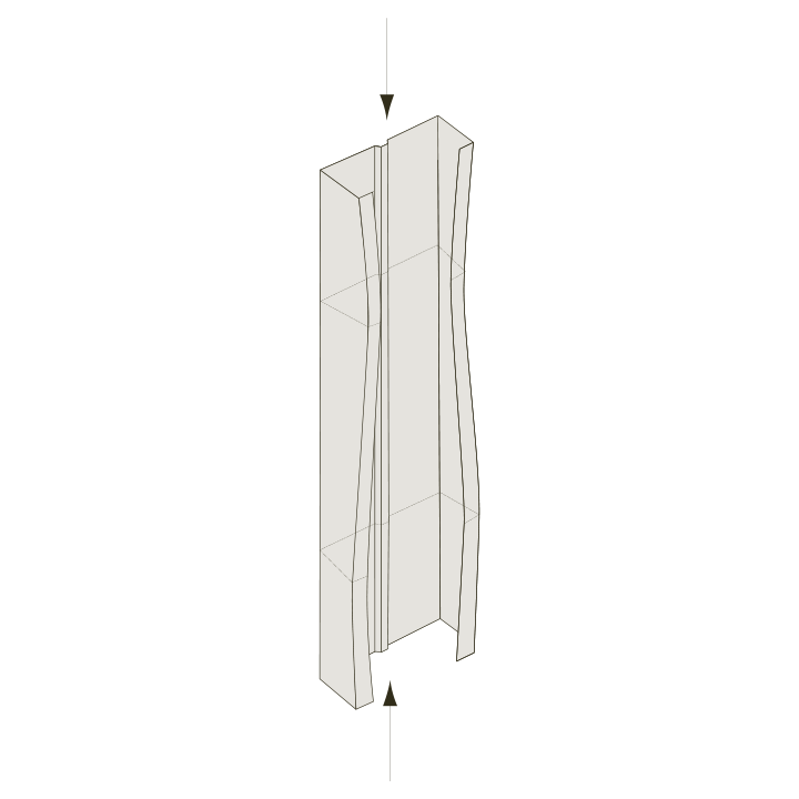
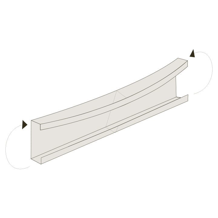
The type of stress that causes instability also influences the classification of instability phenomena, such as shear, compression, flexure, and torsion. Common types of instability include global/flexural buckling, local buckling, patch load buckling, shear buckling, lateral torsional buckling, and flexural torsional buckling.
Common types of instability include global/flexural buckling, local buckling, patch load buckling, shear buckling, lateral torsional buckling, and flexural torsional buckling. These phenomena are covered in the SSAB Design handbook.
3. What are the effects of structural instability?
4. What is local buckling?
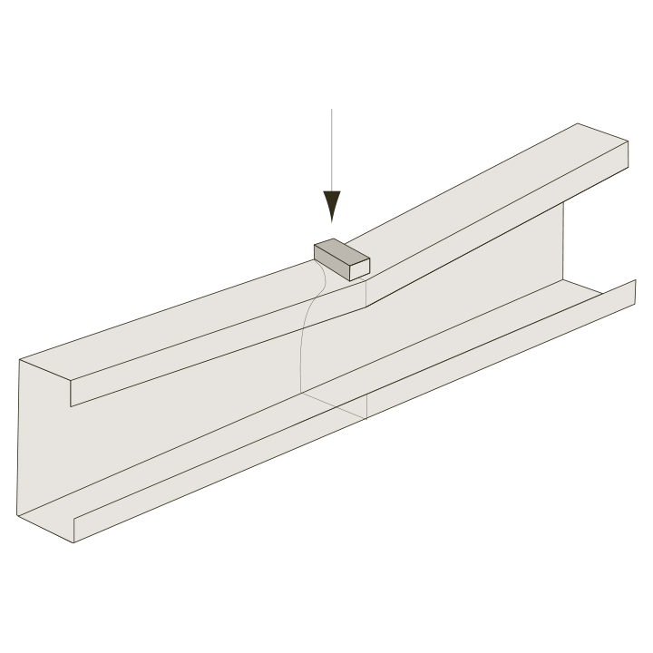
Local buckling is a form of instability that occurs when thin plates are compressed, causing them to buckle and reduce the load-carrying capacity of the structure. However, after buckling, the stresses are redistributed, and the member can still have some additional post-critical capacity.
Modern design codes and standards consider this additional post-critical capacity when calculating the load resistance of the structure with regard to local buckling. The load capacity depends on several factors, such as the slenderness ratio, yield strength, boundary conditions, load type, residual stresses, and geometric imperfections. To ensure adequate structural performance, it is essential to account for local buckling during the design phase.
5. What is global or flexural buckling?
Flexural or global buckling is a type of instability that can occur in slender structures such as columns or beams when a compressive load is applied. This instability affects the entire length of the structure and is therefore a global phenomenon. When flexural buckling occurs, the entire structure can buckle, potentially leading to sudden failure without any warning.
Because of the critical nature of global/flexural buckling, it is essential to consider this phenomenon during the design process to ensure the stability, safety, and functionality of the structure. To mitigate the effects of buckling of a member, useful measures include increasing the member's effective length, increasing the section's resistance to buckling or applying lateral restraints.
6. What is distortional buckling?
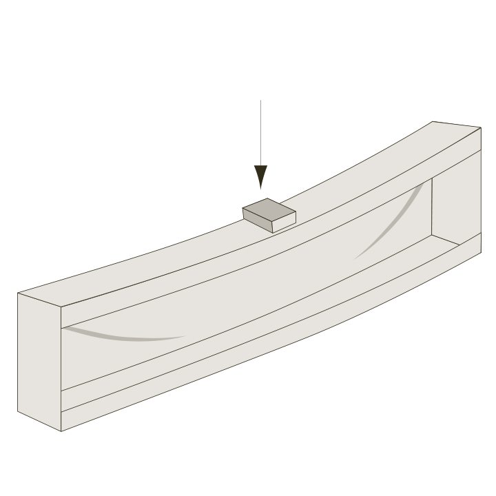
Distortional buckling is a type of instability that can occur in stiffeners like grooves or edge folds used to support slender plates and increase their resistance to local buckling. If the stiffener is not strong enough to resist the internal forces on it, the flange or web can experience local buckling, which significantly reduces the member's load capacity. The magnitude and direction of the applied loads, as well as the dimensions and material properties of the stiffener, affect the degree of distortion. Distortional buckling is sometimes also referred to as local distortional buckling or stiffener buckling.
To prevent distortional buckling, it is important to ensure that the stiffeners are adequately designed and sized to resist the internal forces. This can be achieved through appropriate choice of material, sizing, and shape of the stiffeners.
7. What is lateral-torsional buckling?
Lateral torsional buckling is a type of instability that occurs in beams subjected to bending, causing the compressive flange to bend and twist in a lateral direction. This affects the whole length of the structure, and sudden failure can occur when critical loads are exceeded.
To prevent lateral torsional buckling, several measures can be taken during the design and construction process. One approach is to add construction elements to restrain the compression zone of the beam. Other prevention measures include applying the load to the tension part, increasing the width or thickness of the compressive flange of the beam, or using closed cross-section geometries. Fully fixed end connections can also improve beam performance regarding lateral torsional buckling.
8. What is patch loading instability?
Patch loading instability is a local failure phenomenon that can occur in a girder web when a concentrated force is introduced perpendicular to the girder flange. This failure can significantly reduce the capacity of the entire beam. Resistance to patch loading failure depends on factors such as load distribution, flange dimensions, material properties, and geometric imperfections.
For fixed loads, adding transverse stiffeners to a girder can often address the problem by providing additional support to prevent the web from failing. However, for moving loads, adding transversal stiffeners may be neither practical nor cost-effective, and other measures may need to be considered. One such measure is to use thicker webs or to reinforce the web with longitudinal stiffeners to increase the load capacity. Advanced Finite Element Analysis (FEA) can also be used to simulate the susceptibility of the girder to patch loading instability and to optimize the design to prevent it.
9. What is shear buckling?
Shear buckling is a type of instability that can occur in slender plate surfaces when they are subjected to shear stresses. When shear buckling occurs, the post-buckling shear capacity of the member should be considered. Post-buckling shear capacity depends on various factors, such as the geometrical and mechanical properties of the member and the boundary conditions. Shear buckling can result in a significant reduction in the load capacity of the structure, and lead to sudden failure without warning.
To prevent shear buckling, designers can take several measures during the design and construction process. One approach is to increase the thickness of the plate or to use materials with higher strength properties to increase resistance to shear stresses. Additionally, adding stiffeners or bracing elements can be used to increase plate stability and reduce susceptibility to shear buckling.
Analytical calculations or advanced Finite Element Analysis (FEA) can be used to predict the susceptibility of the plate to shear buckling and to optimize the design to prevent it. Testing can also provide valuable data for understanding the behavior of the structure and validating design assumptions. It is essential to consider shear buckling in the design of structures that are subjected to shear stresses to ensure structure safety and reliability.
10. What are the main factors driving instability?
The two primary factors driving instability are the magnitude of the stress and the slenderness of the structural element concerned. Slenderness is a measure of how easily a structural element buckles, and is typically defined by the geometry, e.g. width over thickness, and stress distribution of the element. The way a structural element is supported, and the material properties, as well as imperfections, such as minor defects or deviations from the intended shape, also significantly affect the ability of the structure to resist instability.
To prevent instability in structures, engineers need to consider several aspects during the design and construction phases. Proper design analysis should be performed to ensure that the structure can withstand the anticipated loads and environmental conditions. The choice of material and the sizing and shape of the structural elements need to be optimized to ensure they are able to resist instability, while taking account of their slenderness and other factors that affect their stability. It is also important to consider the support boundary conditions of the structural element and any possible imperfections that can affect its stability. Regular inspections and maintenance are also necessary to detect any signs of instability early on and to take appropriate measures to address them.
11. What is the difference between local and global buckling?
Local buckling refers to the buckling of a small part of a structural member, typically thin plates, or shells, that are subjected to compressive stress. In contrast, global buckling, such as flexural buckling, refers to the overall buckling of a structural member due to compressive stresses acting along its entire length.
It is important to distinguish between these two types of buckling, as they have different causes and can lead to different failure modes in the member. Note that instability, in addition to global/flexural buckling and local buckling, also includes patch load buckling, shear buckling, lateral torsional buckling and flexural torsional buckling.
12. How can the resistance of a structural member to local buckling be improved?
Resistance to local buckling is mainly determined by the slenderness ratio of a structural member, such as a flange or web plate in a beam, which is the width divided by the thickness. Geometric imperfections and residual stresses can also contribute to local buckling.
To increase local buckling resistance, it is preferable to introduce reinforcements, also known as stiffeners, in the compressed flange or web plates in the cross-section of the member, such as grooves or edge folds. This can reduce the slenderness ratio without increasing the weight or compromising the load capacity of the member. Increasing the thickness or reducing the width of the member can also reduce the slenderness ratio, but these options may result in increased weight or reduced load capacity.
13. How can the flexural buckling resistance of a structural member be increased?
One way to increase the flexural buckling resistance of a member is to reduce its slenderness by decreasing the buckling length. This can be achieved by bracing the member to divide it into smaller parts. Changing the support conditions is another way to increase resistance. Additionally, increasing the cross-sectional area and thereby member stiffness also improves flexural buckling resistance.
14. What are the instability phenomena with a normal tensile load?
15. How can the local buckling resistance of a flange in a square section design exposed to bending be increased?
The local buckling resistance of a flange under compression is a function of plate slenderness. Reduce plate slenderness by decreasing the width-to-thickness ratio of the plate concerned. This can be achieved by making the section narrower (lower width), increasing the thickness, or introducing a longitudinal stiffener, such as a groove or a welded stiffener, that divides the plate width into smaller parts.
16. How can the local buckling resistance of a flange in a C-section design exposed to bending be increased?
The local buckling resistance of a flange under compression is affected by the element slenderness. A flange plate with a high width-to-thickness ratio is more prone to local buckling under bending loads.
To increase the local buckling resistance of a flange in a C-section design exposed to bending, the width-to-thickness ratio of the flange plate can be reduced by narrowing the section or increasing the plate thickness. Another option is to introduce a local stiffener located on the unsupported flange edge under compressive stresses, such as an edge fold. This stiffener will help to reduce flange plate slenderness and improve its local buckling resistance.
17. What factors must be considered to prevent both local buckling and overall buckling when round tubes are subjected to compressive stresses?
Both local and overall buckling must be considered simultaneously to prevent collapse when designing round tubes to resist compressive stresses. It is important to consider all potential collapse mechanisms, such as snap-through or plastic collapse, and to ensure that the tube material has sufficient strength and ductility. Snap-through is a type of sudden buckling failure where the structure undergoes a rapid and violent transition from a stable state to a highly deformed and unstable state.
Local buckling occurs when the diameter-to-thickness ratio exceeds a certain value, the support conditions and cross-section geometry of the tube must be designed to resist the applied loads. Note that contrary to other geometries, there is no post-critical resistance after buckling has occurred in round tubes. To prevent local buckling, the tube's slenderness ratio must be limited and imperfections in the form of geometric deviations and residual stresses must be minimized.
Global buckling occurs mainly as a result of the tube’s material, length, support conditions, and bending stiffness, which is determined by the cross-section geometry.
18. When are wires weight efficient for lifting applications?
Wires are weight efficient for lifting applications when the parts are subjected solely to tensile stresses. However, selecting the appropriate wire material, diameter, and lifting mechanism configuration is crucial to ensure safe and efficient lifting operations.
Wires have a high strength-to-weight ratio, meaning they can carry a large amount of tension with low weight. However, wires cannot take compression, bending or shear loads. The diameter of the wire should be chosen based on the maximum load capacity and the required safety factor. When choosing the wire material, factors such as the wire's strength, ductility, corrosion resistance, and fatigue resistance should be considered.
In addition, the lifting mechanism configuration should be designed to ensure that the wire is not overloaded or damaged during lifting operations. Consider the angle of the wire, the number of wires used, and the attachment points, as well as the environment, such as temperature, humidity and exposure to corrosive materials, in which the wire will be used. Furthermore, follow applicable industry standards and regulations to ensure safe and reliable lifting operations.
19. Can instability phenomena be accounted for in numerical simulations, such as FEA?
As with all simulations, the challenge is to interpret the results and decide if they provide a good estimation of the actual structure. Any finite element analysis (FEA) focusing on instability calculations should consider imperfections in the structure (residual stresses and geometrical imperfections), non-linear material behavior and the solver / FE package should be appropriate to make the calculations. The results should also be evaluated with regard to the buckling modes, and which simulated modes are plausible with regard to the actual structure.
20. How are residual stresses related to instability resistance?
Residual stresses are stresses that remain in a material after subjection to external loads or treatment. These stresses act like pre-stressing, thereby pre-loading the structure affecting its response to external loads.
Compressive residual stresses generally decrease resistance to instability phenomena driven by compressive stresses because they add to the compressive loads, thereby decreasing the critical load required to trigger instability.
In contrast, tensile residual stresses are less commonly associated with instability, but can act beneficially by opposing any compressive load and subsequently increasing the external load capacity with regard to instability.
21. How are geometric imperfections related to instability resistance?
Even small geometric imperfections, such as out-of-plane deformation or waviness, can significantly affect the instability resistance of a plate and lead to buckling and collapse of the structure under an external load. Out-of-plane geometric imperfections can create local deformation or warping, which increases the compressive stress on the plate. This increased stress can exceed the critical limit required to trigger instability, leading to structure failure.
To ensure stability and prevent collapse, it is crucial to consider and control geometric imperfections during the structure design and fabrication phases.
Analytical calculations or Finite Element Analysis (FEA) can be used during the design phase to predict the effect of imperfections on the stability of the structure. Regular inspections during the service life of the structure can also help to identify and address any potential geometric imperfections, thereby ensuring long-term stability and safety.
22. What are the measures for avoiding patch loading instability?
Patch loading instability occurs when the supporting parts under a concentrated load (or "patch load") lose stability, causing even small increases in the load to produce large deflections and ultimately failure.
One way to avoid patch loading instability is to increase the length of the plate or beam that the load is applied to. This spreads the load out over a larger area, reducing stress concentration at the point of loading. Additionally, reducing the slenderness of the parts becoming unstable can help to prevent patch loading instability. This might involve reducing the height of the component, or increasing the thickness of the plate, alternatively adding stiffeners. Taking these steps may make it possible to increase the patch loading resistance and so avoid instability.
The information in this report is only applicable to SSAB’s products and should not be applied to any other products than original SSAB products.
This report provides general results and recommendations for SSAB steel products. This report is subject to SSAB’s Terms of Use. It shall be the user's responsibility to verify that the information contained herein is correct and is suitable to be used for the particular purpose and application of the user. The report is intended to be used by professional users only who possess adequate expertise, qualification and knowledge for the safe and correct use of the results and recommendations in this report. This report is provided “as is”. The use of the report is at user’s own discretion and risk and that users will be solely responsible for any use of this report. SSAB disclaims any liability for the content or potential errors of this report, including but not limited to warranties and condition of merchantability or fitness for a particular purpose or suitability for individual applications. SSAB shall not be liable for any kind of direct or indirect damages and/or costs related to or arising therefrom, whether special, incidental, consequential or directly or indirectly related to the use of, or the inability to use, the report or the content, information or results included therein.
