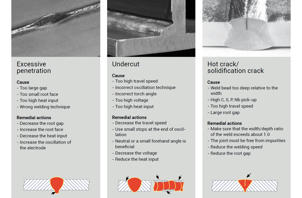
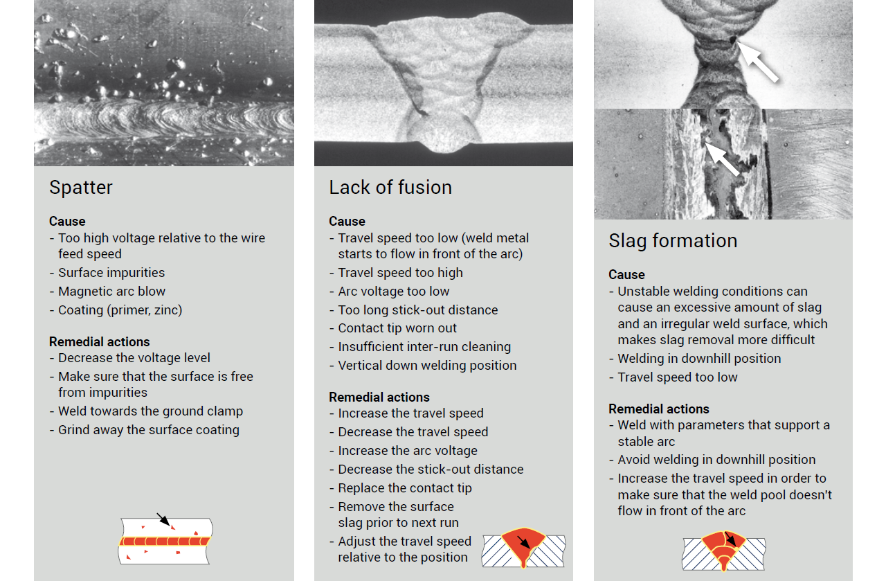
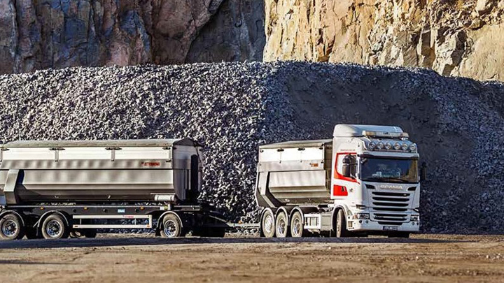
Based on our experience the number one cause of fatigue failures in trailer chassis is due to poor weld quality. Therefore, it is important, not only to thoroughly evaluate the new upgraded design, but also to secure the production process. Poor weld or edge quality will rapidly decrease the service life of any trailer.
Edge quality
Our experience has shown that the primary cause of fatigue failures in trailer chassis is poor weld quality. Therefore, it is vital to not only thoroughly evaluate the new upgraded design, but to secure the production process. Poor weld or edge quality will rapidly decrease the service life of any trailer.
Edge quality also impacts fatigue resistance, and different cutting methods result in different edge qualities. The graph below shows the results of fatigue testing Strenx® 700MC where the plate edge has been milled, laser-cut and sheared. Laser-cut edges are often better than mechanically cut edges. To achieve good fatigue strength with mechanically cut edges, it is important to remove all visual crack-like defects. Modern thermal cutting processes like laser or high-definition plasma generally produce edges in Strenx® 700MC with good fatigue properties. The ranking of such methods from a fatigue perspective would be laser, plasma and gas-cutting. To avoid fatigue problems, it is also important to place start and stop positions in low-stress areas. Blasting of a structure with cut edges normally has a positive effect on fatigue resistance.
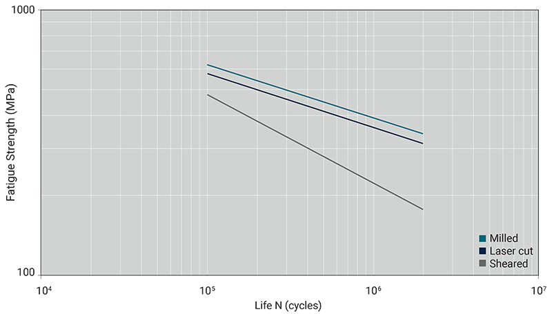
Results from fatigue testing Strenx® 700MC with different edge conditions.
Welding methods and filler material
Typical welding methods
All conventional welding methods can be used for HSS. The most commonly used welding methods in the trailer industry today are:
- MAG welding (with solid or cored wire)
- Submerged arc welding (sometimes used to produce longitudinal beams)
Filler metal
The strength of the filler material should normally be matched to the strength of the base material, as in the table below. However, welds in trailer applications are rarely subjected to stress levels that require matching filler metal. In most cases, it is therefore possible to use undermatching filler metals. If submerged arc welding is used for welding HSS, basic flux is recommended.| Steel Grade | MAG Welding (GMAW) | Submerged Arc Welding (SAW) |
|---|---|---|
| Strenx® 700MC | AWS: A5.28 ER100S-X | AWS: A5.23 F10X |
| AWS: A5.28 ER110S-X | AWS: A5.23 F11X | |
| EN 12534: G Mn3Ni1CrMo | EN ISO 26304-A S69X | |
| EN 12543: G Mn4Ni2CrMo | ||
| AWS: A5.28 ER110S-X | ||
| AWS: A5.28 ER120S-X | ||
| EN 12534: G Mn3Ni1CrMo | ||
| EN 12543: G Mn4Ni2CrMo |
Welding heat input
Strenx® hot-rolled high-strength structural steel
High-strength steels are somewhat sensitive to high heat inputs. Excessively high heat input de-creases the strength as well as the impact tough-ness of the welded joint. If the minimum yield strength of the base material must be achieved in the welded joint, the maximum recommended heat input should not exceed the values in the graph below.
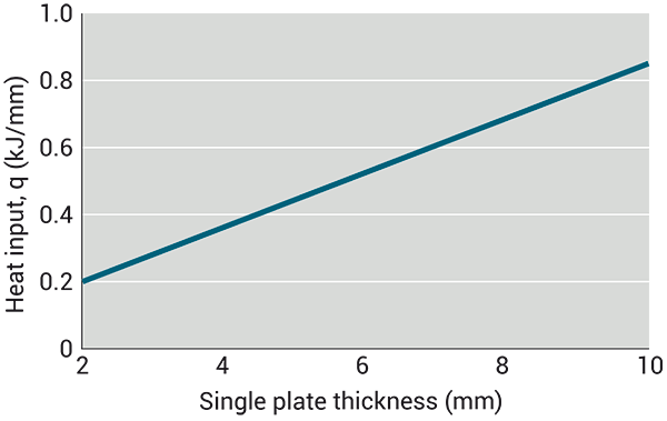
Maximum recommended heat input (Q) for Strenx® 700MC in order to fulfill the minimum yield strength (Re) and impact toughness requirements at -40 °C.
The graph is valid for butt welds, welded with matching filler metal, and where the reinforcement has been removed before testing. The maximum interpass temperature is 100 °C. The heat input can be calculated according to the formula:

Q = Heat input (kJ/mm)
k = Arc efficiency (-)
U = Voltage (V)
I = Current (A)
v = Travel speed (mm/min)
The arc efficiency values are 0.8 for MAG welding and 1.0 for SAW welding. If the weld is located in a low stressed area and the impact toughness requirement is of minor importance, higher heat inputs can be used.
Strenx® cold-rolled high-strength structural steel (CR)
Strenx® CR is produced in thinner gauges, making it more difficult to increase the heat power enough to limit the heat affected zone to a level that will allow for a failure of the base material. As a rule of thumb: weld with as low a heat input as possible.
Welding distortion
Strenx® hot-rolled high-strength structural steel
In practice, for trailer applications, distortion due to welding is more critical than the static strength of the welds. Follow these tips to minimize the amount of distortion due to the welding operation:
- Weld with as low a heat input as possible
- Minimize the cross sectional area of the weld, as in the illustration below
- Prebend, clamp or angle the parts before welding in order to compensate for the shrinking
- Avoid irregular gaps in the root
- Use symmetrical welds, as in the illustration below
- Minimize reinforcements and optimize the throat thickness of the fillet welds
- Weld from rigid areas to loose ends
- Optimize the welding sequence

Cross-section of the weld and how it influences the angle deviation.
Use a symmetrical welding sequence.
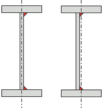
To avoid a curved or deformed longitudinal beam after welding of the web, displace the web in relation to the center of the flange. This makes it possible to locate the longitudinal welds in the neutral layer of the flanges, as in the illustration below.
Displacing the web in relation to the flange makes it possible to weld in the neutral layer of the flange, which avoids deformations from welding.
Strenx® cold-rolled high-strength structural steel (CR)
In order to avoid heavy deformation of Strenx® CR steels, follow these guidelines:
- Weld with as a low heat input as possible.
- Use a wire with a small diameter (0.8 mm).
- Downhill welding technique reduces the heat input and is recommended if permitted by the application and the production conditions.
- If the application allows a small gap between the welds, intermittent welding can be used.
- If the application requires a sealed connection, silicon or adhesives could be used instead of welding to seal the connection and prevent corrosion to arise.
- Use lap welds instead of butt welds.
- Welding of thin sheets requires a short distance between the tack welds (80–120 mm).
- Power sources for MAG welding have greatly evolved, making it possible to weld thin sheets with approximately 50% lower heat input.
- If the joint is accessible from both sides, resistance spot welding can be used instead of fusion welding.
- Avoid welding and use mechanical joining, which ensures very low or no deformation.
Hot straightening
Hot straightening is a very common method to restore longitudinal beams for trailer chassis that have been distorted due to welding. Hot straightening is not recommended for Strenx® and Strenx® CR. This is because the steel may lose its guaranteed properties in the heated area.
The recommended maximum temperature these steels can be subjected to without loosing their guaranteed mechanical properties is:
- Strenx® 700MC: 650 °C
- Strenx® 700 CR: 300 °C
- Strenx® 960 CR: 200 °C
Welding quality
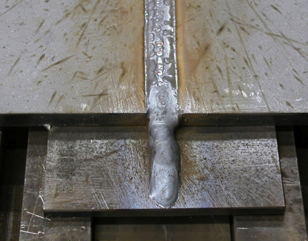
If the flanges of the longitudinal beam have to be welded (which is not recommended) in order to increase the length of the flange or beam, use a temporary sacrificial plate for critical weld starts and stops. The temporary plate can easily be re-moved by grinding after welding. See photo below.
Pay attention to the stops, which are placed on the sacrificial plate. This plate is then removed by grinding.
Welding with rutile cored wires has the tendency to create very smooth transitions between the weld metal and the base material. This property could be used in order to increase the fatigue performance of the weld, especially in critical areas like the landing gear attachment and the hanger bracket attachments.
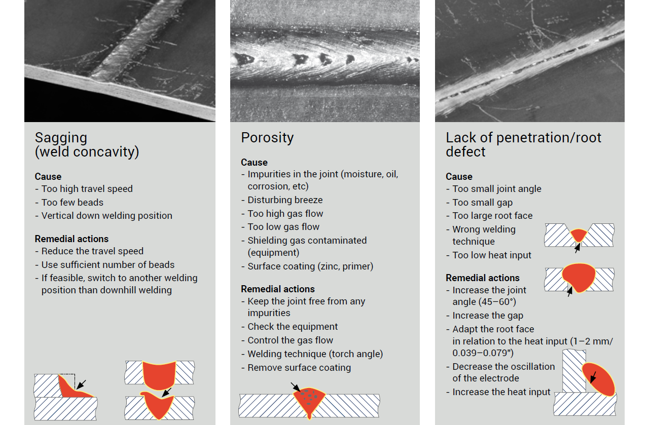
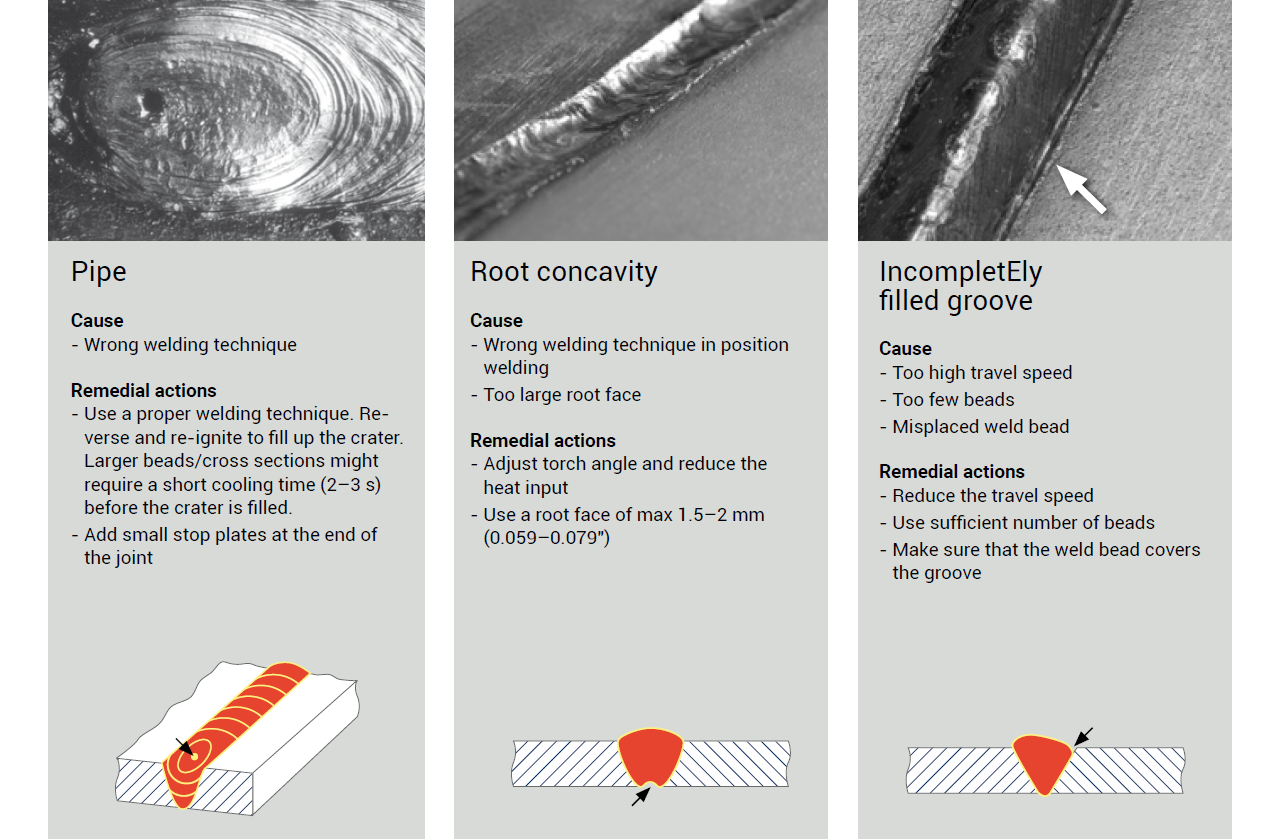
To secure the weld quality, it is important to examine all welds. Defects that are especially detrimental for the fatigue performance of the trailer are surface-breaking weld defects such as:
- Undercuts
- Root defects
- Lack of fusion
- Cold laps
- All types of cracks
Proper direction of the grinding scratches oriented longitudinal to the stress.
The information in this report is only applicable to SSAB’s products and should not be applied to any other products than original SSAB products.
This report provides general results and recommendations for SSAB steel products. This report is subject to SSAB’s Terms of Use. It shall be the user's responsibility to verify that the information contained herein is correct and is suitable to be used for the particular purpose and application of the user. The report is intended to be used by professional users only who possess adequate expertise, qualification and knowledge for the safe and correct use of the results and recommendations in this report. This report is provided “as is”. The use of the report is at user’s own discretion and risk and that users will be solely responsible for any use of this report. SSAB disclaims any liability for the content or potential errors of this report, including but not limited to warranties and condition of merchantability or fitness for a particular purpose or suitability for individual applications. SSAB shall not be liable for any kind of direct or indirect damages and/or costs related to or arising therefrom, whether special, incidental, consequential or directly or indirectly related to the use of, or the inability to use, the report or the content, information or results included therein.

